





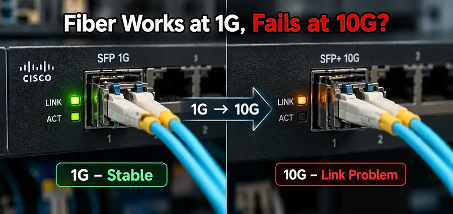
A Fiber Link that works perfectly at 1Gbps does not necessarily guarantee reliable operation at 10Gbps. This is a common situation in enterprise networks: two switches communicate without errors through an existing fiber connection at 1G, but after replacing the transceivers with 10G SFP+ modules or upgrading the switch ports (mainly Cisco switch) , the link becomes unstable, experiences packet loss, shows interface errors, or does not come up at all. In some cases, the 10G connection establishes successfully but delivers surprisingly poor performance.
The reason is that 10 Gigabit Ethernet places significantly stricter requirements on the entire optical path. Fiber type, transceiver wavelength, cable quality, connector cleanliness, insertion loss, optical power levels, distance, patch panels, and even bends in the fiber can become important when moving from 1G to 10G. Therefore, when a Fiber Link works at 1G but fails at 10G, replacing the transceiver immediately is not always the correct troubleshooting approach. The complete optical path should be examined.
Why Can the Same Fiber Link Behave Differently at 1G and 10G?
The most important point is that a working fiber cable is not automatically a suitable fiber cable for every Ethernet speed. A 1G Fiber Link operates at a much lower data rate than a 10G connection. When the speed increases to 10Gbps, signal integrity requirements become more demanding. Problems that were insignificant at 1Gbps may become visible when the same infrastructure carries ten times the data rate.
This is particularly important in older buildings and network installations where fiber cabling may have been installed years ago for Gigabit Ethernet. The infrastructure might contain older multimode fiber, multiple patch panels, questionable splices, worn connectors, or patch cords whose specifications are unknown. The link can therefore appear completely healthy at 1G while having insufficient optical performance for reliable 10G operation.
Fiber Type Can Determine Whether 10G Works Correctly
One of the first things to check when troubleshooting a Fiber Link is the type of fiber being used. Fiber cables are broadly divided into single-mode and multimode categories. Single-mode fiber such as OS2 is commonly used for longer-distance connections, while multimode fiber such as OM1, OM2, OM3, OM4, and OM5 is commonly found in shorter building and data-center connections.
Not all multimode fiber generations provide the same 10G performance. For example, OM3 and OM4 are widely used with 10GBASE-SR. OM3 can generally support 10GbE over distances up to approximately 300 meters, while OM4 can extend this to approximately 400 meters under the applicable 10GBASE-SR specifications.
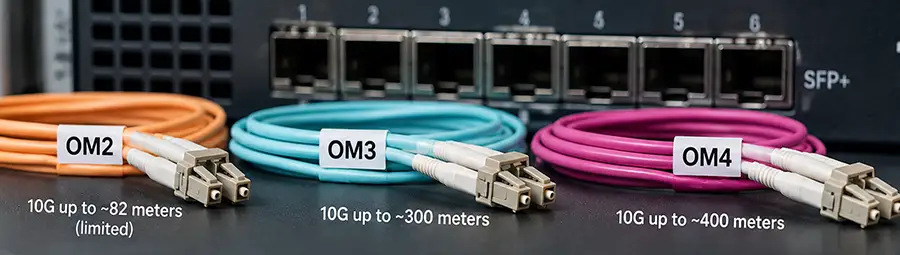
Older OM1 and OM2 installations have considerably more restrictive distance limits for 10GbE. This creates a classic troubleshooting scenario: an existing multimode Fiber Link operates normally at 1G, but installing 10G SR transceivers causes instability or prevents the link from establishing. The cable has not suddenly become defective. The requirements have changed.
1G SFP and 10G SFP+ Transceivers Are Not the Same
Another common mistake is assuming that upgrading from 1G to 10G simply means installing faster versions of the same optical modules. A 1G SFP and a 10G SFP+ transceiver may look almost identical physically, but their optical and electrical specifications can be different. The wavelength, transmitter characteristics, receiver sensitivity, supported fiber type, maximum distance, and optical budget all matter.
Consider a network using 1000BASE-LX transceivers over single-mode fiber. If the network is upgraded to 10GBASE-LR, the existing OS2 infrastructure may be perfectly suitable, assuming the total link loss and distance remain within specification.
However, replacing a 1G multimode solution with 10GBASE-SR requires greater attention to the multimode fiber category and total channel design. A Fiber Link should therefore be evaluated as a complete system rather than assuming that changing both modules from SFP to SFP+ is sufficient.
The Wrong Fiber and Transceiver Combination Can Cause Problems
The transceiver installed at each end must match the fiber infrastructure. 10GBASE-SR is designed primarily for multimode fiber and commonly operates around 850 nm. 10GBASE-LR, on the other hand, is designed for single-mode fiber and typically operates around 1310 nm.
Using inappropriate fiber, unsupported distances, incompatible optical modules, or mismatched transceivers can result in a link that does not come up or behaves unpredictably. Both ends of the Fiber Link should also use compatible optics. For example, an SR module should normally communicate with another appropriate SR module over the correct multimode fiber path. An LR connection should use compatible LR optics and suitable single-mode fiber.
The module label alone should not be the only thing checked. Wavelength, supported standard, fiber type, connector type, and distance should all be verified.
Optical Loss Becomes an Important Part of Troubleshooting
Every optical connection introduces some amount of signal loss. Fiber length contributes attenuation, but connectors, adapters, patch panels and splices can also increase total insertion loss. Dirty or damaged connectors can introduce substantially more loss than expected.
Imagine a Fiber Link running through several patch panels before reaching the remote switch. At 1G, the received optical power may still remain comfortably inside the operating range of the receiver. After upgrading the connection to 10G with different optics and a different optical budget, the same physical path may become marginal.
This is why simply checking whether the fiber cable is physically connected is not enough. The important question is whether the optical signal reaching the receiver falls within the supported receive-power range of the installed transceiver.
Check Tx and Rx Optical Power
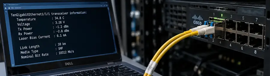
On managed enterprise switches, Digital Optical Monitoring, often called DOM or DDM, can provide valuable information about the transceiver and optical signal. Depending on the module and platform, administrators may be able to monitor transmit power, receive power, temperature, voltage and laser bias current.
Rx power is particularly useful when diagnosing a problematic Fiber Link. If received power is close to or below the receiver’s minimum specification, the connection may become unstable or fail entirely. Extremely high received power can also cause problems because optical receivers have maximum input limits.
The readings should therefore be compared against the specifications of the exact transceiver model rather than judged simply as “high” or “low.” For Cisco environments, optical monitoring commands can often help determine whether the issue is likely related to the physical optical path before cables or modules are replaced.
Dirty Fiber Connectors Can Work at 1G but Cause Trouble at 10G
Contaminated connectors are one of the most underestimated causes of fiber network problems. Dust, oil and microscopic contamination on an LC connector can increase insertion loss and affect optical performance. A connection may continue operating at 1G despite this additional loss, especially if there is sufficient optical margin.
After upgrading the Fiber Link to 10G, the reduced margin may expose the problem. This is why fiber inspection and proper cleaning are standard troubleshooting procedures in professional fiber installations. Disconnecting and reconnecting a dirty patch cord repeatedly is not a proper cleaning method and can potentially make contamination worse.
If an existing fiber path has been operating for years, inspecting and cleaning both ends before investigating more complicated causes can save considerable troubleshooting time.
Patch Cords Can Be the Hidden Problem
The permanent fiber installed inside the building is not always responsible for a failed 10G upgrade. Sometimes the problem is simply the short patch cord connecting the switch to the fiber patch panel. Older installations may contain OM1, OM2 or unidentified multimode patch cords mixed with newer OM3 or OM4 infrastructure. A network engineer may inspect the main cable and confirm that it is OM3 while overlooking an old patch cable at one end of the Fiber Link.
The complete path matters. For a multimode 10G connection, the fiber segments and patch cords should be appropriate for the intended optical standard. Replacing questionable patch cords with known, correctly specified cables is therefore a useful diagnostic step.
Excessive Bending Can Increase Fiber Loss
Fiber cables should not be bent sharply. A tight bend can cause optical power to escape from the fiber and increase attenuation. The effect depends on the fiber construction, wavelength and severity of the bend. This problem frequently appears inside crowded racks where patch cords are tightly wrapped around cable managers, trapped behind equipment, or bent sharply immediately after leaving an LC connector.
If a Fiber Link becomes unstable after equipment is moved or a rack is reorganized, checking the physical routing of the patch cable is worthwhile. A cable that looks intact externally can still experience optical performance problems due to poor routing or excessive bending.
Why Can a 10G Fiber Link Come Up but Still Be Slow?
A successful link light does not prove that the connection is healthy. Sometimes both 10G ports show an active link while actual throughput remains poor. Users may experience packet loss, retransmissions or inconsistent transfer speeds. In this situation, interface statistics become extremely important.
CRC errors, input errors, packet drops and other counters can indicate a Layer 1 problem even when the interface remains up. The network should also be checked for configuration issues such as MTU inconsistencies, interface settings, congestion or problems elsewhere in the traffic path. If a direct test between the same two devices works correctly with a short known-good fiber cable but fails through the building infrastructure, the permanent Fiber Link becomes a strong troubleshooting focus.
A Practical Way to Isolate the Problem
When a 1G connection works but 10G does not, changing several components simultaneously makes troubleshooting more difficult. A controlled test is much more useful. The two switches can first be connected using known-good compatible 10G transceivers and a short, correctly specified fiber patch cord. If the 10G connection operates normally, the switches and transceivers are much less likely to be the cause.
The original Fiber Link can then be reintroduced. If the problem immediately returns, attention should shift toward the patch panels, permanent cabling, connectors, splices and patch cords that make up the installed fiber path. Optical Tx/Rx readings and interface error counters should then be checked at both ends. This approach separates equipment problems from cabling problems and prevents unnecessary replacement of working SFP+ modules.
Should You Use OM3 or OM4 for a 10G Fiber Link?
For new multimode 10G installations, OM3 and OM4 are common choices. Both are designed to support high-speed optical networking, but OM4 provides greater bandwidth capability and supports longer 10GBASE-SR distances than OM3. For short rack-to-rack or equipment-room connections, either may be suitable when used within the relevant specifications.
For longer runs or installations that may later require faster technologies, the overall cabling strategy should consider future bandwidth requirements rather than focusing only on today’s 10G connection. Single-mode OS2 is another important option, particularly for longer distances and infrastructure designed for long-term scalability. The appropriate choice depends on distance, optics, existing cabling and future network plans.
Fiber Link Troubleshooting Before Replacing the SFP+
When a 10G upgrade fails, the SFP+ module is often blamed first. In practice, replacing optics without testing the rest of the link can waste both time and money. The correct approach is to verify the transceiver specifications, confirm that both ends use compatible modules, identify the fiber category, inspect patch cords and connectors, check the total distance, review DOM optical levels and examine interface error counters.
A known-good short cable test is particularly valuable because it provides a simple reference point. If the equipment works correctly in a controlled short-distance test, troubleshooting can concentrate on the installed fiber infrastructure.
Conclusion
A Fiber Link working perfectly at 1Gbps but failing after an upgrade to 10Gbps is not unusual. The most important thing to understand is that successful 1G operation only proves that the optical path meets the requirements of that particular 1G connection. It does not prove that the same infrastructure meets the requirements of 10 Gigabit Ethernet. Fiber category, transceiver type, wavelength, link distance, optical budget, connector condition, patch cords, splices, bending and Tx/Rx optical power can all influence the result.
Even a link that comes up at 10G can still suffer from physical-layer problems that appear as errors, packet loss or poor throughput. Instead of immediately replacing the SFP+ modules, test the Fiber Link systematically. Start with known-good optics and a short known-good cable, compare the results with the permanent fiber path, check optical power at both ends and examine interface counters.
This process usually reveals whether the real problem is the transceiver, the fiber infrastructure or another part of the network. For businesses upgrading from 1G to 10G networks, ITMan can assist with fiber troubleshooting, Cisco switch configuration, SFP and SFP+ compatibility checks, and on-site network diagnostics in Dubai.